
Static routes can be configured on a router so that it understands how to route traffic to networks not directly attached to it. Let’s use the following topology as an example:
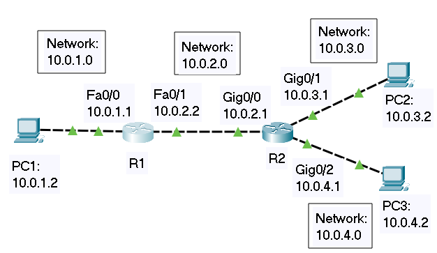
For this lab, I set up a simple topology in Packet Tracer with two routers (R1 and R2) and three PCs (PC1, PC2, PC3) so I could practice adding static routes.
There are four networks set up:
- Network 10.0.1.0/24 – Consists of PC1 and the Fa0/0 interface on R1.
- Network 10.0.2.0/24 – Consists of the interface Fa0/1 on R1 and Gig0/0 on R2.
- Network 10.0.3.0/24 – Consists of the Gig0/1 interface on R2 and PC2.
- Network 10.0.4.0/24 – Consists of the Gig0/2 interface on R2 and PC3.
Keep in mind that each connected interface on a router is part of a network, so don’t forget the network that exists between R1 and R2.
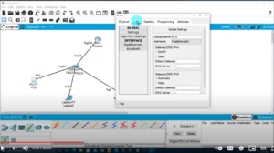
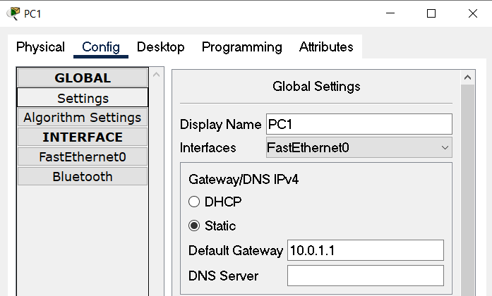
After deciding on the ranges I would use for each network, I assigned an IP address and default gateway for each PC. In Packet Tracer, you just need to click on each PC and choose the “Config” tab in the window.
First, you’ll want to set up the Default Gateway, which for PC1, is 10.0.1.1. This is the Fa0/0 interface on R1.
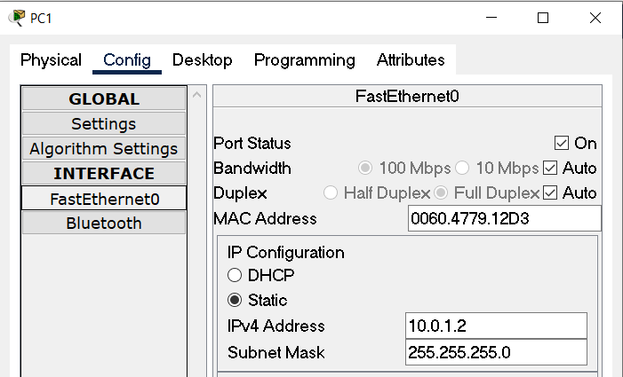
Next, I statically set the IP address and subnet mask of each PC by choosing the appropriate interface from the options on the left of the window. In the case of PC1, it looks like the following.
I repeated the process for each PC and that completed the configuration necessary for them.
Next, I added IP addresses to each router interface and brought each interface up. To do this in Packet Tracer, click on the router and choose the “CLI” tab from the top of the window. Issue the necessary commands to get to interface configuration mode as follows:
Router1>en
Router1#conf t
Enter configuration commands, one per line. End with CNTL/Z.
Router1(config)#int
Router1(config)#interface fa
Router1(config)#interface fastEthernet 0/0
Now, set the IP address of the interface and bring the interface up by issuing the “no shutdown” command.
Router1(config-if)#ip address 10.0.1.1 255.255.255.0
Router1(config-if)#no shut
Once I had repeated this process for each interface on each router, I was ready to begin moving packets through the networks.
The first thing I did was ping PC2 from PC3. The ping was successful because R2 is directly connected to the networks of each of these PCs so the router had automatically added each network to its routing table.
When you configure the IP addresses on the interfaces of a router, the router will automatically add routes corresponding to the addresses into the routing table. This is because the router is directly connected to these networks.
Then I pinged the Gig0/0 interface for R2 which has the IP address of 10.0.2.1. This ping was also successful because R2 is also directly connected to the 10.0.2.0 network with that interface.
Next, I tried pinging the Fa0/1 interface on R1 at 10.0.2.2. This failed because, although R1 is directly connected to R2, it’s not yet aware of the 10.0.3.0 and 10.0.4.0 networks. This is where I began to set up static routes.
Before getting the static routes configuration, it’s interesting to note that although the ping from PC3 to Fa0/1 on R1 failed, R1 actually received the pings. You can see this by issuing the “debug ip icmp” command at R1 as follows:
Router1>en
Router1#debug ip icmp
ICMP packet debugging is on
Router1#
After issuing the command, I kept the window for R1 open and opened a window for the PC3 command prompt so I could watch the pings being sent from PC3, see them being received by R1, but failing to return to PC3. It looked like this:
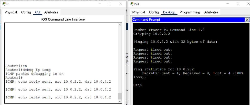
As you can see on the left, the packets made it to R1, but R1 didn’t know how to route the echo reply that would be needed for a successful ping.
This is an interesting point to keep in mind. A successful ping is not just getting packets to a destination. A successful ping shows that a packet can get to the destination and a reply packet can make it back.
After watching that, I made sure I issued the “no debug ip icmp” command at R1 to cancel the debug command.
Now the fun of setting up the static routes began so the routers would know how to route to the networks they are not directly connected to, allowing all the devices to communicate with each other.
Starting with R1, I configured two static routes:
- The first route was to 10.0.3.0/24 with a next hop address of 10.0.2.1. This will allow R1 to be able to route to the network where PC2 resides.
- The second route was to 10.0.4.0/24, also with a next hop address of 10.0.2.1. This will allow R1 to route to the network where PC3 resides.
This only takes 4 steps total.
- Issue the “show ip route” command to view the routing table.
- Issue the “ip route” command with the first destination network address, subnet mask, and next hop.
- Issue the “ip route” command with the second destination network address, subnet mask, and next hop.
- Issue the “show ip route” command to confirm everything has been added to the routing table.
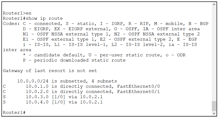
Router1#show ip route
Router1(config)#ip route 10.0.3.0 255.255.255.0 10.0.2.1
Router1(config)#ip route 10.0.4.0 255.255.255.0 10.0.2.1
Router1(config)#do show ip route
I repeated the process for R2 which only needed one static route because that is the only network it is not directly connected to.
Router2#show ip route
Router2(config)#ip route 10.0.1.0 255.255.255.0 10.0.2.2
Router2(config)#do show ip route
I noticed that when I issued the “show ip route” command for each of the routers, the output from R2 had more information. The first image shows the output from R1, the second image shows the output from R2:

The difference is due to the fact that I used different routers each running a different version of the Cisco IOS:
- R1 is a Cisco 1841 router running IOS version 12.4
- R2 is a Cisco 2911 router running IOS version 15.1.
Beginning with IOS version 15, local routes were added to the routing table and they display in the output for the “show ip route” command. Local routes always show up as having a /32 mask (regardless of what subnet was actually configured on the interface) and show the IP address configured on the interface. This is a nice bit of extra information that requires an extra step of issuing the “show ip int brief” command to get that information for versions prior to IOS 15.
After confirming all networks were showing in the routing tables of both routers, from each PC I pinged the other two PCs to confirm everything was working as it should.